I’m continuing my project, and this week we’re focusing on displays and actuators. Let’s begin!
1. Display
Displays are used to display information from embedded systems. There are various types of displays; this time, I’ll be using an OLED.
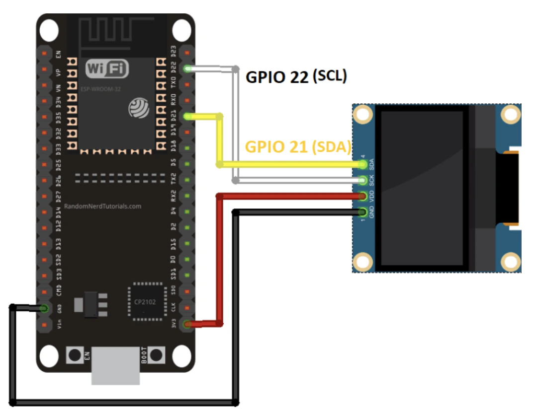
Here’s the wiring I’m using:
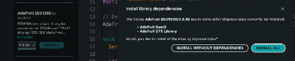
Type "SSD1306" in the search box and install all of the SSD1306 library’s dependencies from Adafruit.
Next, let’s move on to the code in the Arduino IDE. First, open your Arduino IDE and go to Sketch > Include Library > Manage Libraries. The Library Manager should open.
The Adafruit library for the OLED display comes with several functions for writing text. I’ll write "Hello World" in it as an example. This is the code I’m using.
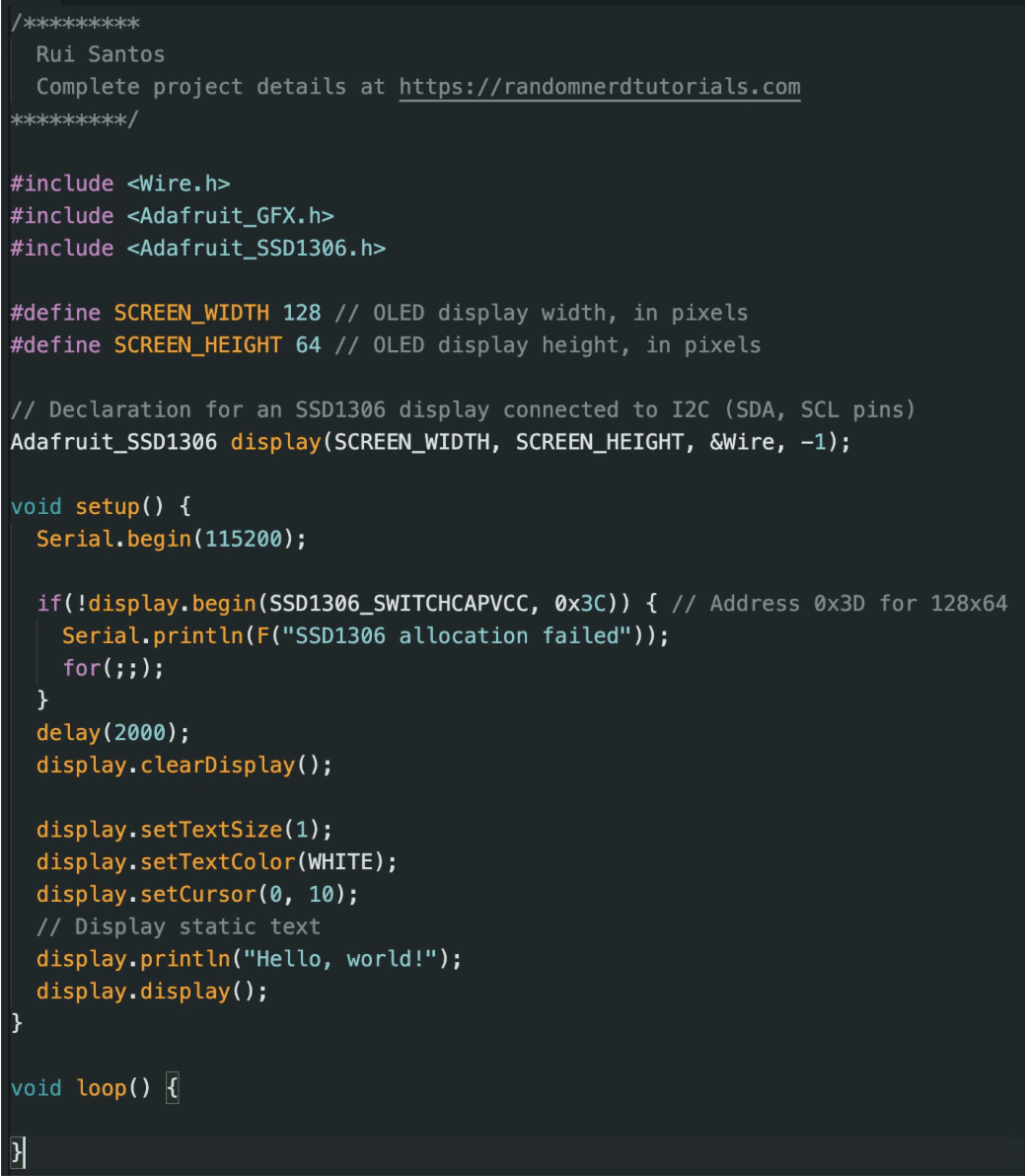
Source: https://randomnerdtutorials.com/esp32-ssd1306-oled-display-arduino-ide/
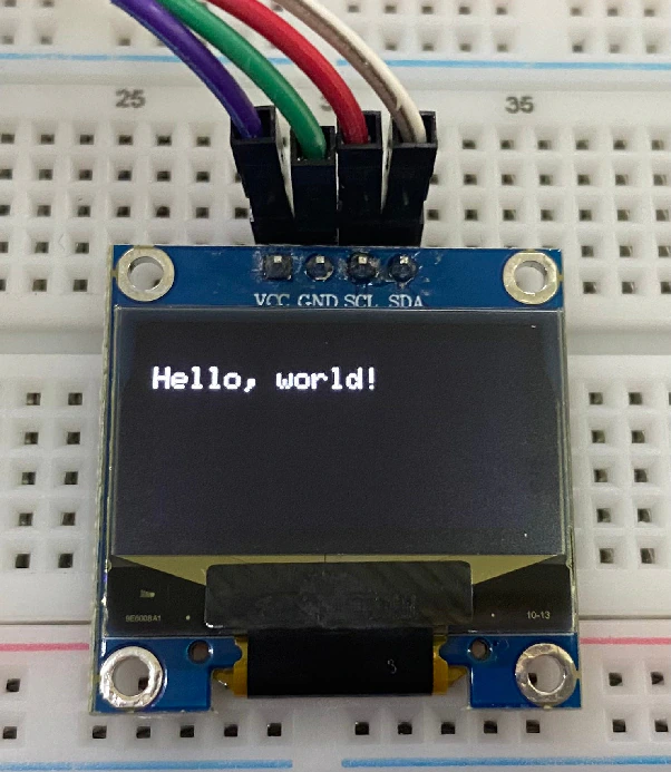
After uploading the code, this is what you’ll get in the OLED:
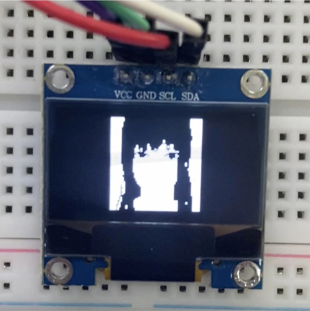
Because I was bored, I wanted to display my favorite character—Asa Mitaka—on the OLED. I used an Image to C Array converter for this. To make it happen, I put the C header file and the Arduino file in the same folder. Don’t forget to include the header.
This is the Arduino code I used:
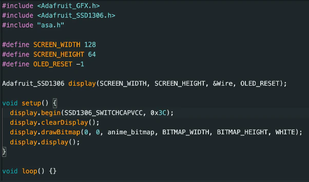
Yeah, done!!! Here’s the result.
2. PWM
Next, I’ll experiment with PWM using LED lights. PWM is a technique for obtaining an analog signal from a digital system; this technique can be used to control the brightness of an LED.
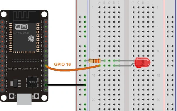
Here’s the wiring configuration of mine.
This is the code I used.
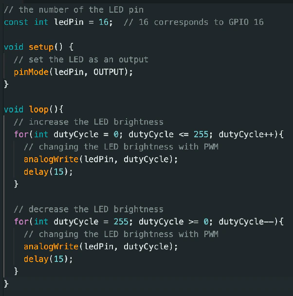
Source: https://randomnerdtutorials.com/esp32-pwm-arduino-ide/