Push,,, Lights,,, ON!
Input and output are essential elements in the IoT world. They act as interfaces for connecting to the outside world. In this session, we will use a push button as an input and an LED light as an output.
The components required:
- ESP32
- Breadboard
- LED light
- Push button
- Jumper cable (male-to-male & male-to-female)
- Resistor (330 ohm)
This is the configuration of my ESP32 digital inputs and digital outputs. To minimize errors and other issues, I suggest using an online lab simulator before jumping into real hardware work. However, it’s up to you.
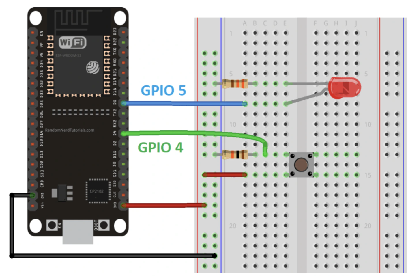
During the process, I encountered some difficulties with the configuration. The LED wouldn’t light up. I repeatedly unplugged and reconnected the ESP32 to the breadboard, until I finally decided to separate them. However, that was not the problem. I carefully analyzed the code, but it seemed fine.
Then, I decided to change the components in case any of them were damaged. After that, I finally realized that the resistors I used were the real problem. They also caused damage to other components, especially the LED. Why? Because resistors function to limit or regulate the flow of electrical current in a circuit by providing a specific amount of resistance, preventing short circuits and protecting the LED.
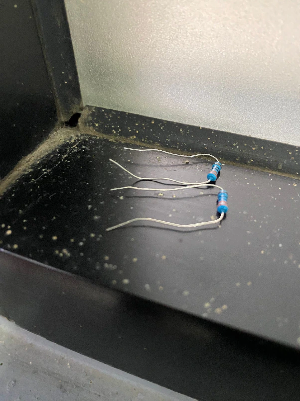
Broken Resistors
Here is the code I used based on my configuration.
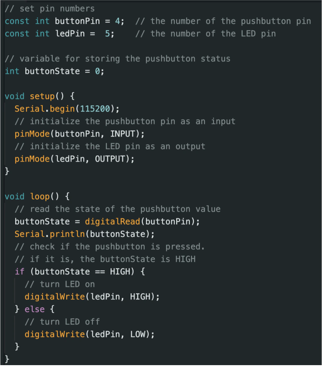
Source: https://randomnerdtutorials.com/esp32-digital-inputs-outputs-arduino/
Finally, it’s done! When I press the push button, the LED lights up red, which indicates success. Here is the result.