Sup, everypony!
My name is Nisrina Zakiyah (Belle) and I will tell you the starting point of my IoT journey. I’m from Information System & Technology, ITB.
My (favorite) lecturer gives us this assignment for this Embedded System course, AND I’M SO EXCITEDDD!!! You may ask "why?" (or maybe do not care). Well that’s because I have an interest in this field—which is the "technical things" like the embedded systems. On the other hand, I also really enjoy writing since forever. I’m so grateful that my lecturer gives me an opportunity to develop my writing skills.
"Ugh, enough yap,"
Alright then, let’s begin! ;3
Last week, I prepared the things needed (namely those in the picture above). Thanks to the lecturers because they have made it easier for us by making a list of links to the items that must be purchased.
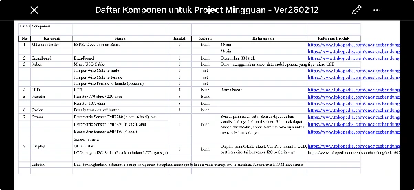
But, for this week, our microcontroller—ESP32, a micro USB cable, and a breadboard (optional) are more than enough. That’s because our only objective is to make the LED lights in the ESP32 blinks.
To make that happen, first, we must prepare the software in our PC/laptop.
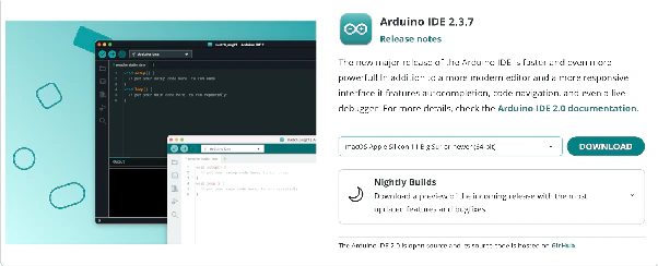
Based on the lecturers agreement, the IDE that we’re going to use is Arduino IDE. This is the installation processes (in the MacOS Apple Silicon):
1. Install Arduino IDE
Go to this website:
https://www.arduino.cc/en/software/
Choose the right operating system for you.
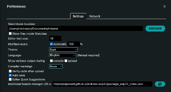
2. Add ESP32 Board Manager URL
Open the app, then click:
Arduino IDE → Settings → Additional Boards Manager URLs
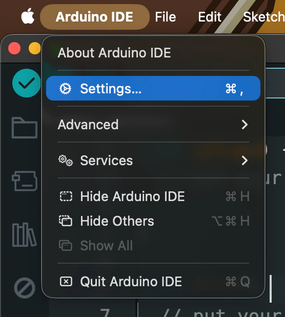
Fill it with this GitHub link:
https://espressif.github.io/arduino-esp32/package_esp32_index.json
3. Install the ESP32 Board Package
Click:
Tools → Board → Boards Manager
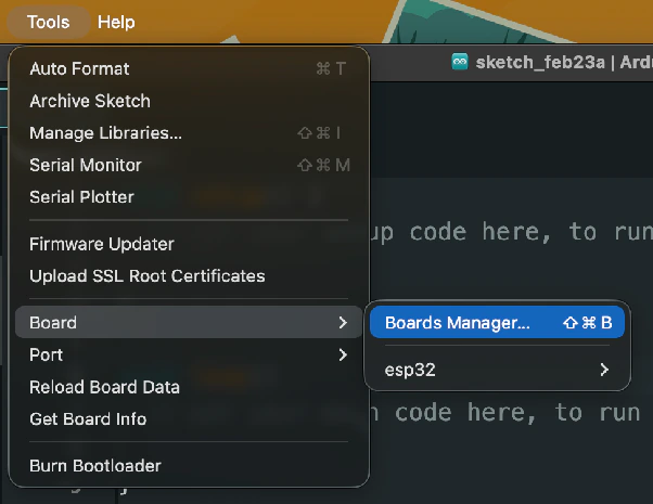
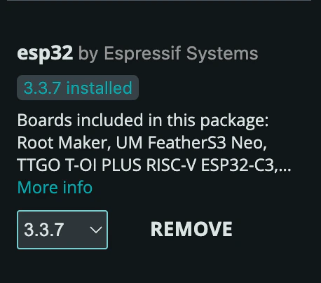
Search "esp32", then install the package created by Espressif Systems.
4. Select Your Board
Click:
Tools → Board → esp32
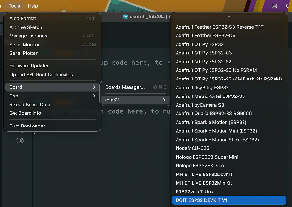
Choose DOIT ESP32 DEVKIT V1.
5. Install the USB Driver
Install the USB to UART driver.
https://www.silabs.com/software-and-tools/usb-to-uart-bridge-vcp-drivers?tab=downloads
6. Connect the ESP32
Connect your ESP32 board to your PC/laptop using a micro USB cable. If you're using a MacBook, you'll also need a USB-C to USB adapter/HDMI hub.
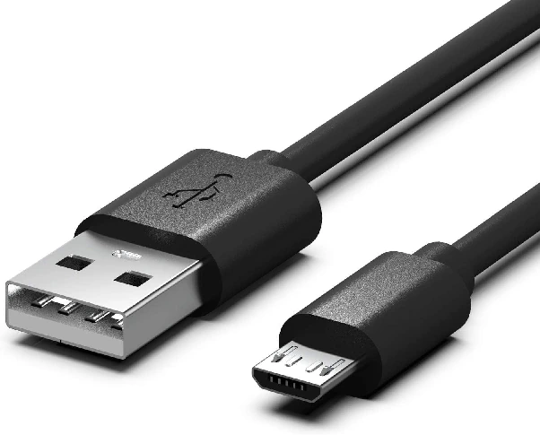
Micro USB cable
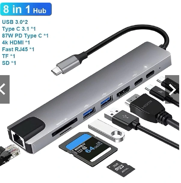
USB-C to USB HDMI cable
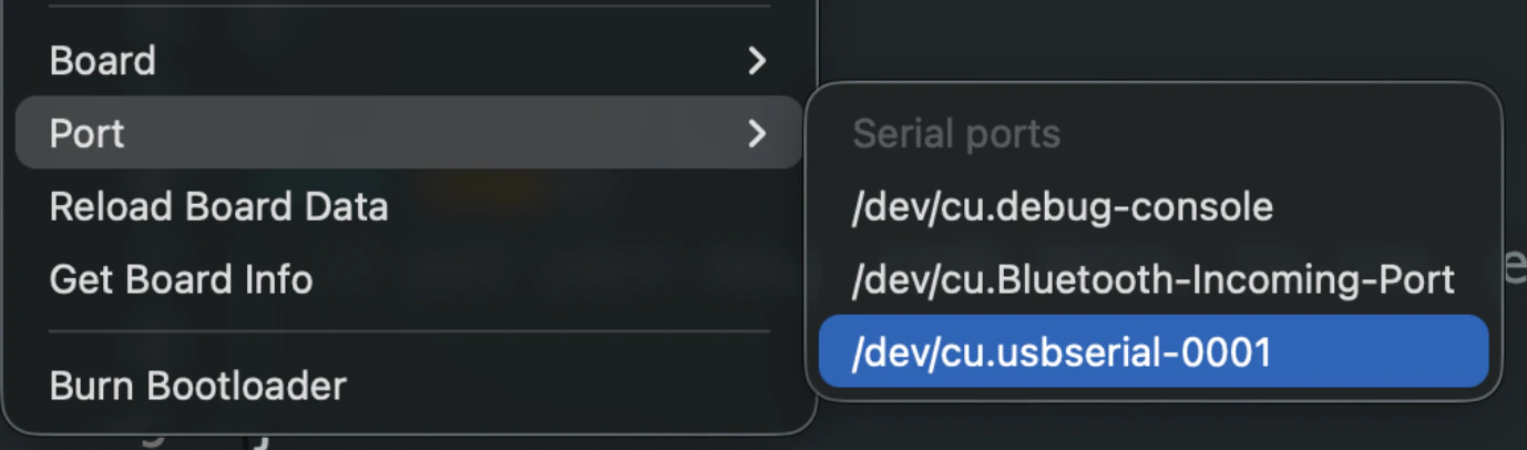
7. Select the Serial Port
After connecting the board, you'll see an additional port under:
Tools → Port
Choose that port (mine says /dev/cu.usbserial-0001).
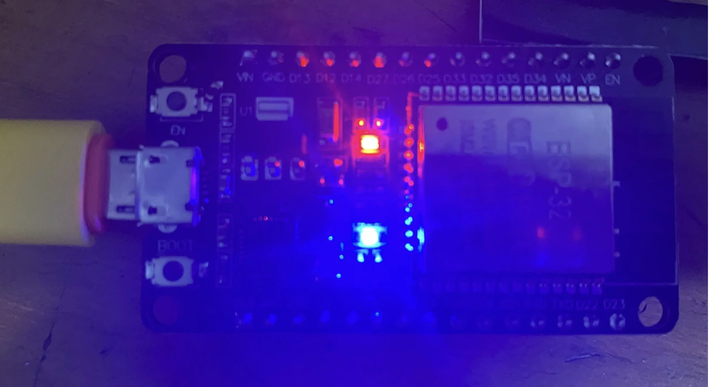
Additionally, your ESP32 LED will glow red like this.
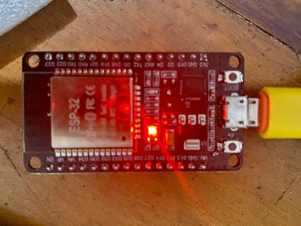
ESP32 glows in red
8. Open the Blink Example
To achieve our goal (making the LED blink), click:
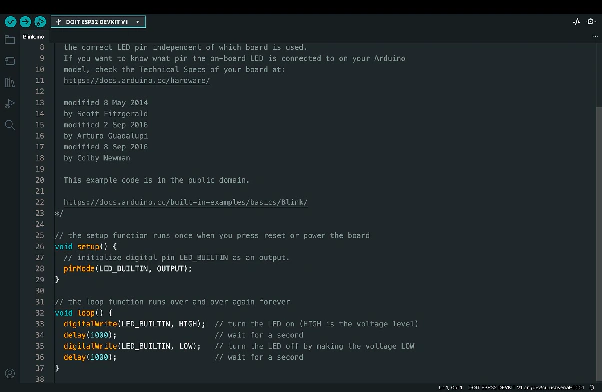
File → Examples → 01.Basics → Blink
Then, Arduino IDE will open the example source code.
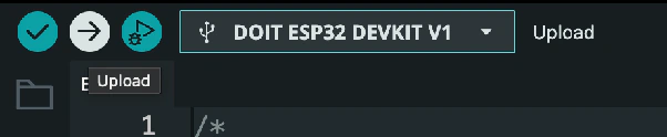
9. Upload the Sketch
Click Upload to compile and upload the sketch.
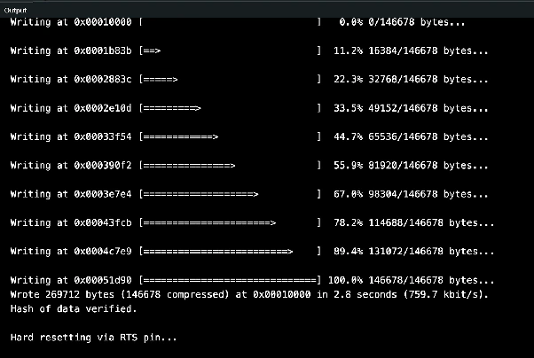
TADA!!! It is successfully uploaded ;333
Here is the result (the blue LED light is blinking):